 FR
FR EN
ENFeatures
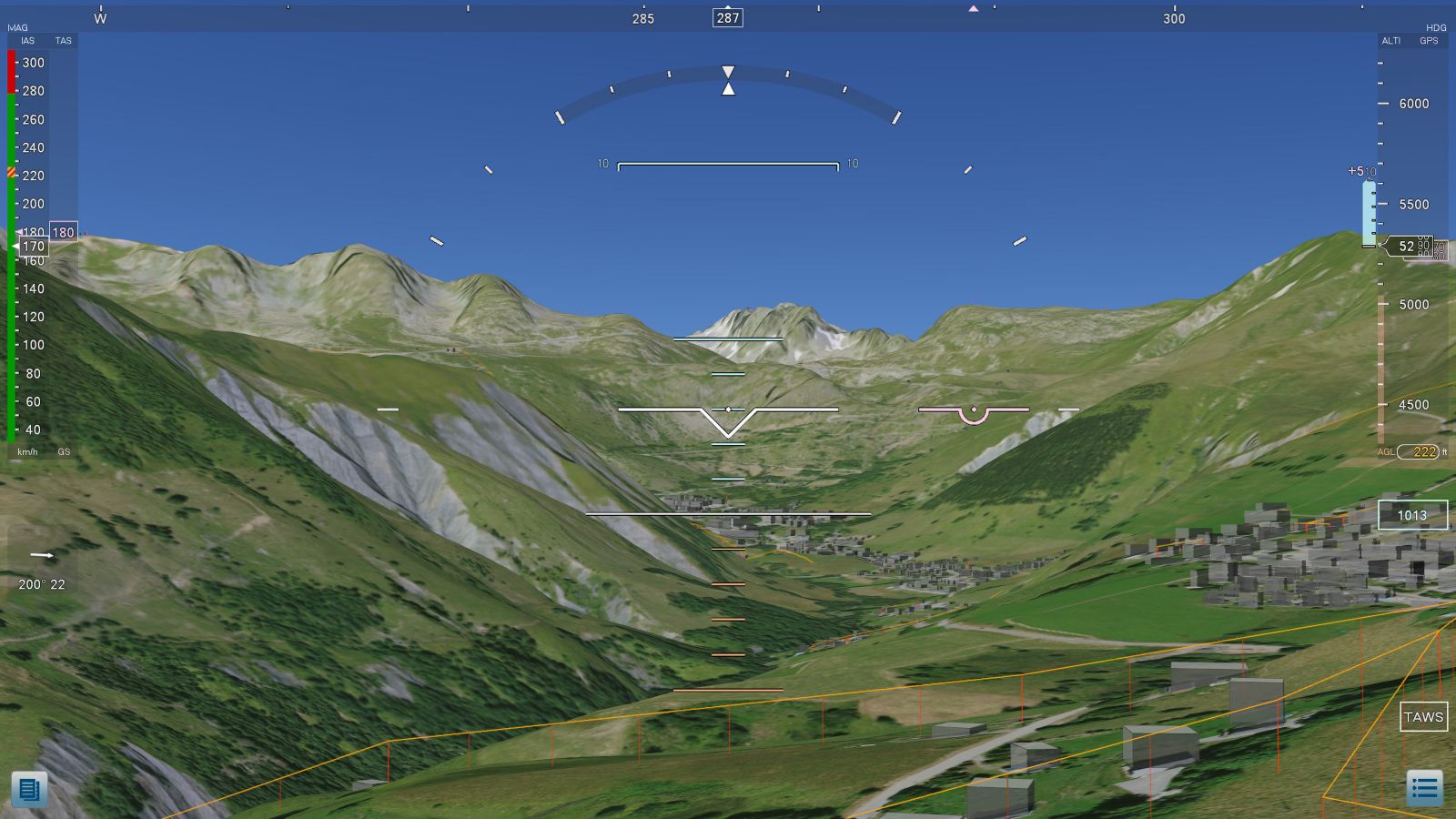
The image generated is based on a "raster" engine that processes orthophotographs and an associated "vector" engine that inserts obstacle data (vector objects).
The orthophotographic source data is in WGS 84, enabling the system to be used worldwide.
This image is "piloted" by AHRS or ARINC 429 network data, and stabilized in relation to the aircraft's line of sight or trajectory.
The zoom level depends on the flight phase (ground or hover, navigation, obstacle alarm, approach).
In the event of an alarm, it is necessary to modify the zoom level to render the image as if the human eye were looking for an obstacle in its field of vision. A 2D view is automatically displayed if the obstacle is not in the visual field of the 3D image.
This zoom is even different during landing, when the pilot concentrates on the end point of his trajectory.
This "head-down" design requires a high degree of realism in the image, to cancel out any interpretation time in the event of an alarm.
The pilot leaves the outside view for only a brief moment.
To achieve this
We use HR 20 cm orthophotographs.
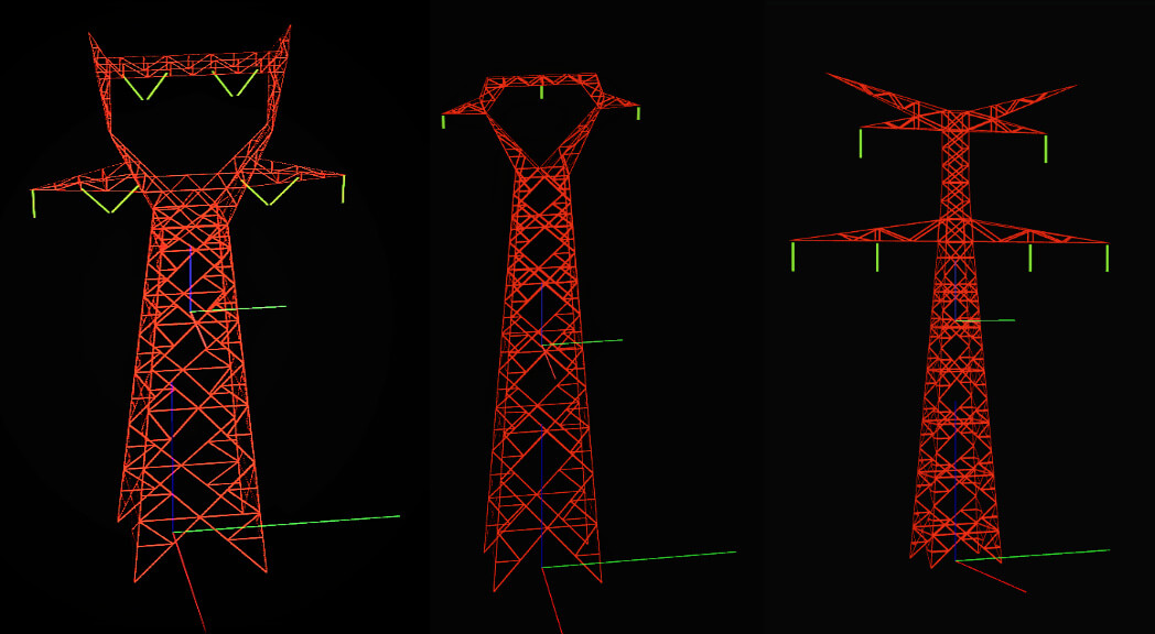
The 3D drawings of the pylons in great detail (644 different models) make it possible to identify,
without ambiguity, the potentially dangerous tower.
Conductor layers are represented and protection volumes are attached to them.
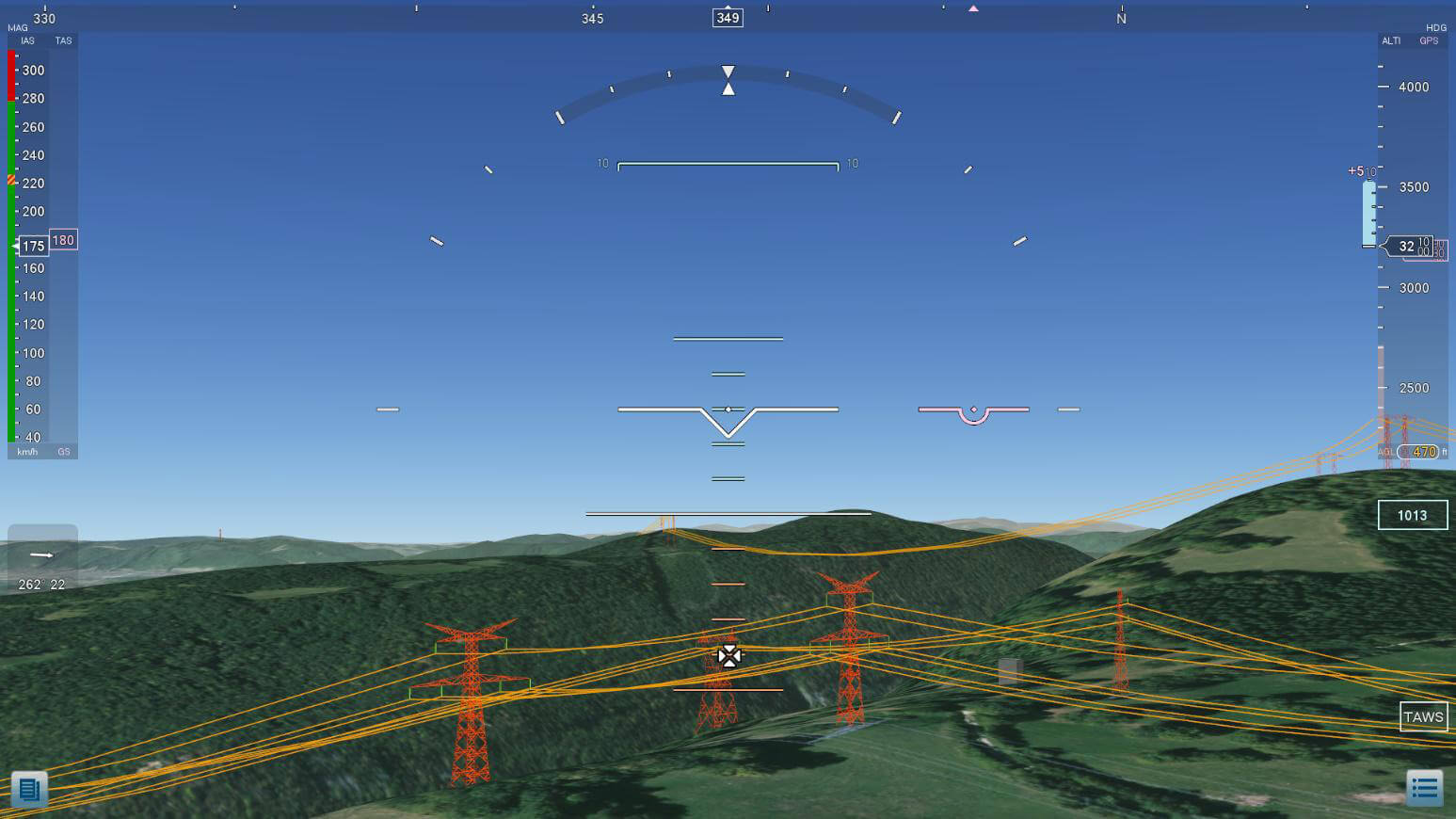
There is a management of electrical wires ... and phase management for isolators.
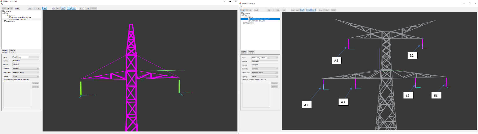
Pylon with 2 wires (Corsica) / Pylon with double power line
The phases are numbered to restore the coherence of the network of electrical wires